Zuk on 38's

Got an vehicle build underway? post up pictures and tell us all how its going!

Builds threads only please.
User avatar
TanZuk
Engaged 4wd low
Engaged 4wd low
Posts: 234
Joined: Thu Jan 05, 2012 11:17 pm
Location: Pompano Beach, Florida US

Re: Zuk on 38's

Post by TanZuk » Thu Mar 01, 2012 12:48 pm

Updates:

Burned in the Panhard/Bumpstop mount in at 12*

Burned in the Modified Ford Shock Tower at 8*

The lower portion of the Bumpstop mount was boxed in. This was to conceal the nuts holding the Heim Joint and the Bumpstop in place. This will also give it more strength and add an additional place for a support bracket for the 1.25 DOM Front Brace Tube.

Working on the bracket that is on the shock side of the mount. This has many compound angles and will be a full box. I will also try and add some holes with support tubes.


Image


Image


Image

User avatar
TanZuk
Engaged 4wd low
Engaged 4wd low
Posts: 234
Joined: Thu Jan 05, 2012 11:17 pm
Location: Pompano Beach, Florida US

Re: Zuk on 38's

Post by TanZuk » Thu Mar 01, 2012 12:50 pm

Panhard Mount Bracket being made. This is the 1st of 3 brackets.

This is the lager bracket and will be partially concealed with the shock. This will make it not as noticeable.

Steps:

Starting pieces needed to be tacked in place because of their irregular shape.
Matting box pieces will be fitted and welded in place.
Bracket will then be removed to weld the inside
Holes will be popped in and support tubes added while it is out.
Final Bracket burn in

Note: Rear side plate still needs to be made to complete the full boxed bracket..


Image


Image


Image


Image

User avatar
TanZuk
Engaged 4wd low
Engaged 4wd low
Posts: 234
Joined: Thu Jan 05, 2012 11:17 pm
Location: Pompano Beach, Florida US

Re: Zuk on 38's

Post by TanZuk » Thu Mar 01, 2012 12:53 pm

This has been an interesting bracket to make. There were no parallel surfaces on any of the pieces and there were a few compound angles. The shapes looked more like a kite then a bracket.

The first 2 steps are done.

Steps:

Starting pieces needed to be tacked in place because of their irregular shape.
Mating box pieces will be fitted and welded in place.
Bracket will then be removed to weld the inside
Holes will be popped in and support tubes added while it is out.
Final Bracket burn in


The pieces will be welded together while it is still on the frame. The tacks will then be cut off the frame to make it easier to work on bracket for the holes, installing the support tubes and weld the inside for strength.


Image


Image


Image

User avatar
TanZuk
Engaged 4wd low
Engaged 4wd low
Posts: 234
Joined: Thu Jan 05, 2012 11:17 pm
Location: Pompano Beach, Florida US

Re: Zuk on 38's

Post by TanZuk » Thu Mar 01, 2012 12:55 pm

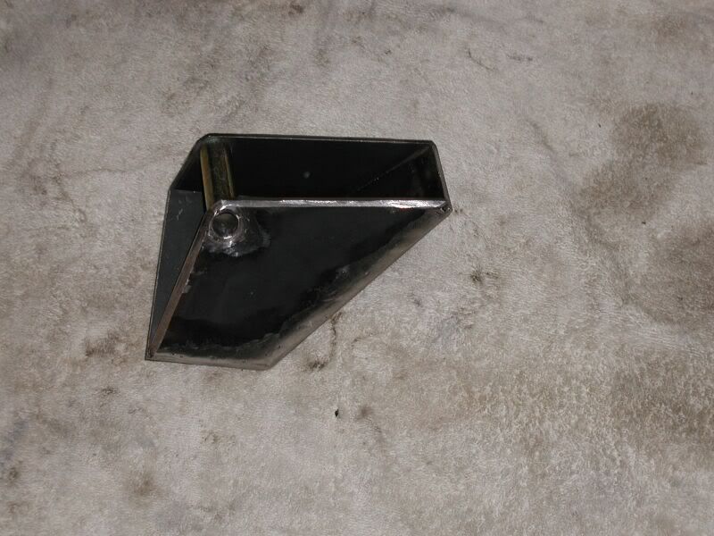
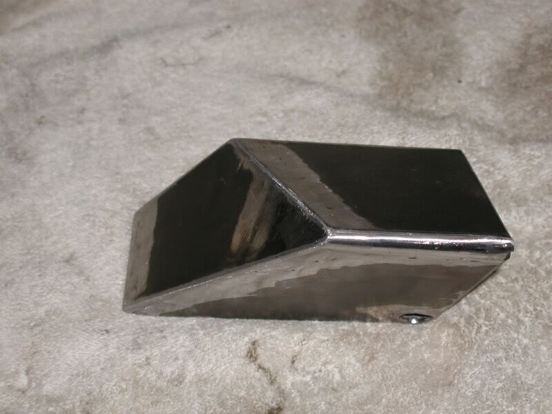
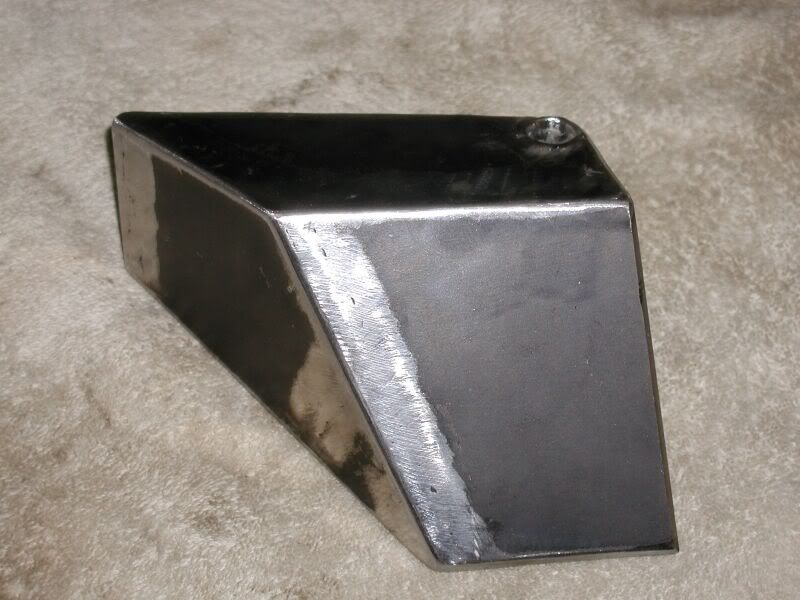
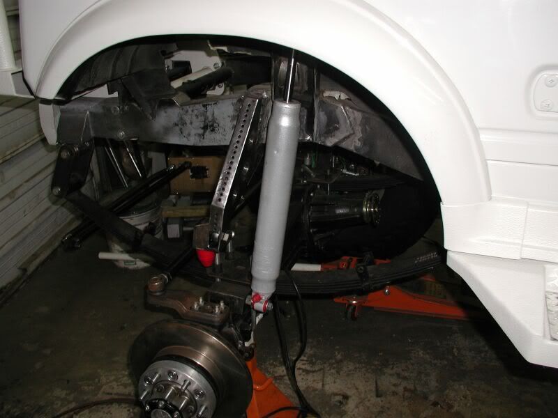
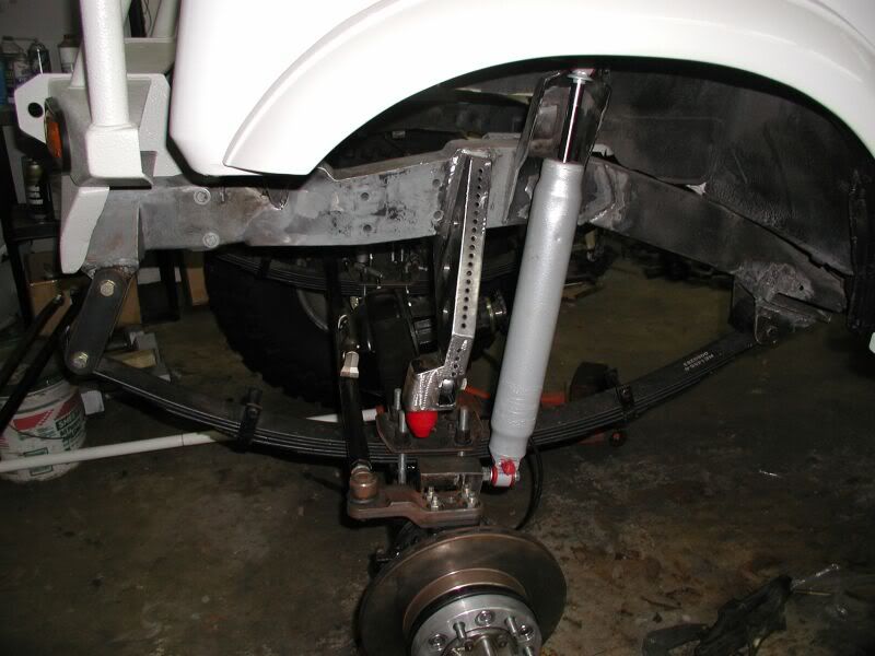
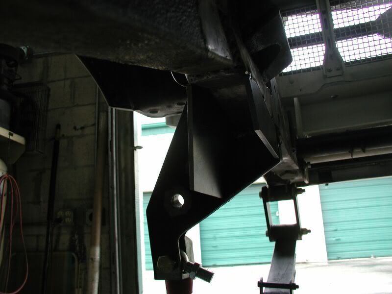
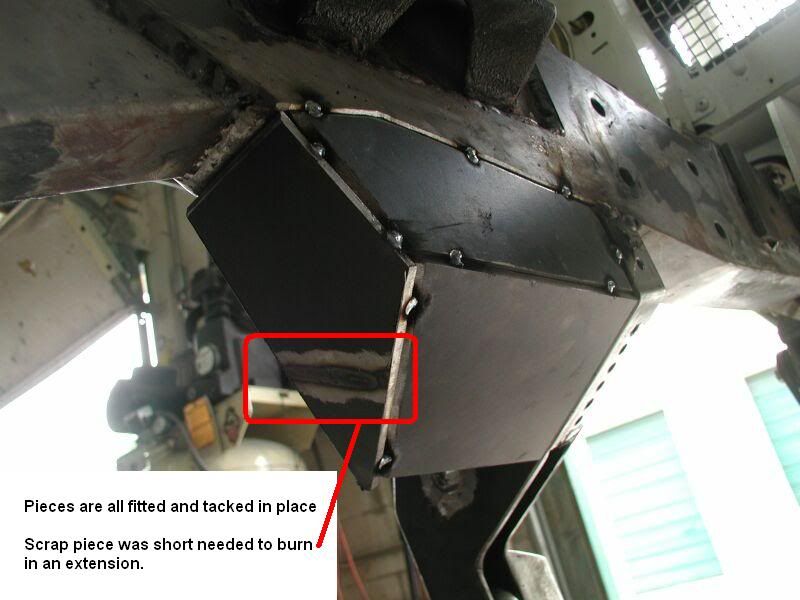
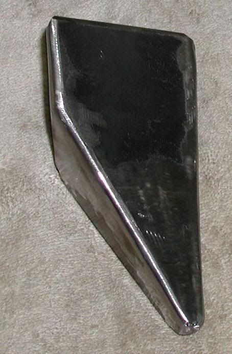
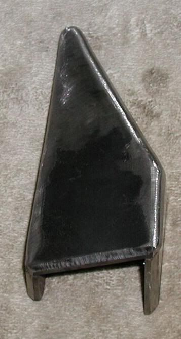
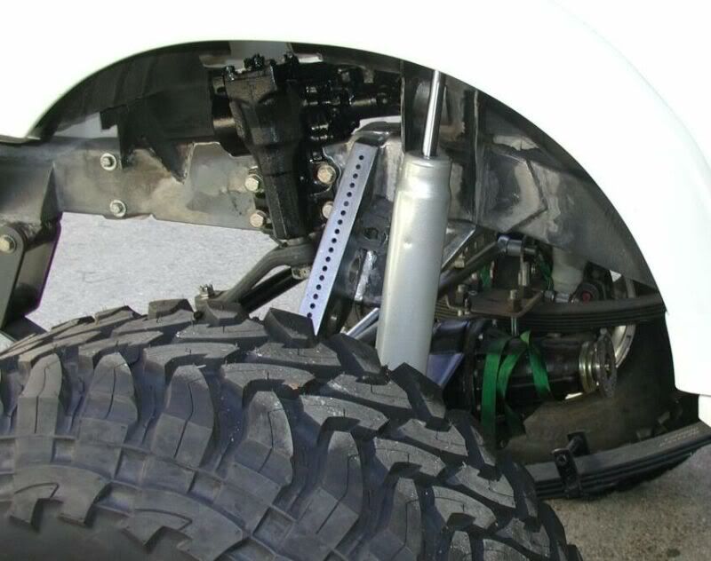
Here is a look at the large Panhard bracket which is a perfect example of a 3D trapezoid.

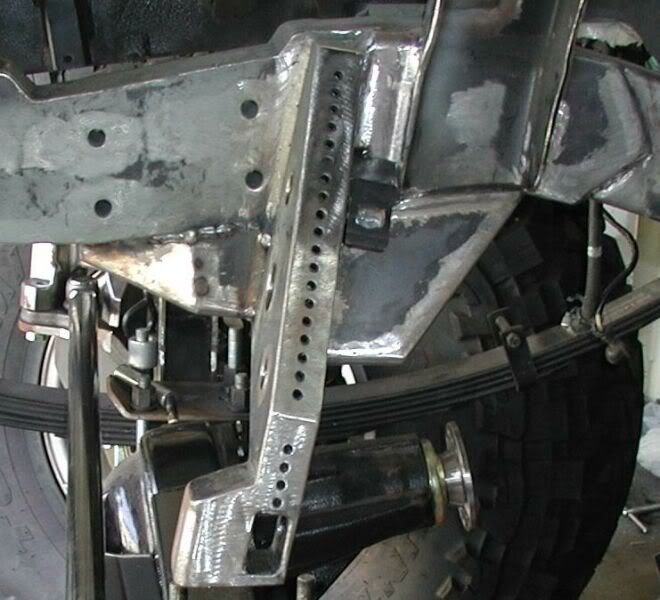
It took a little longer to complete after collaborating with Jethrobodean on the best structural strength of the bracket location. He had pointed out with the bracket blending in at the end of the fishplate. This would cause extra stress on this area. The better option would be to keep it 1 to 1.5” away from the end of the fishplate.

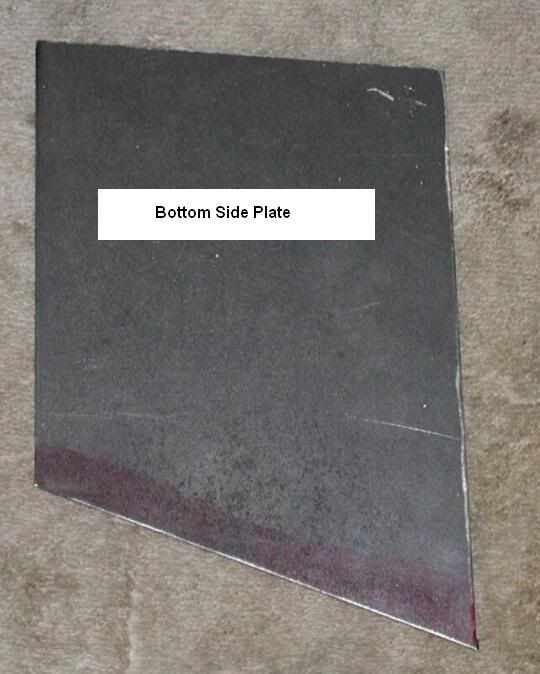
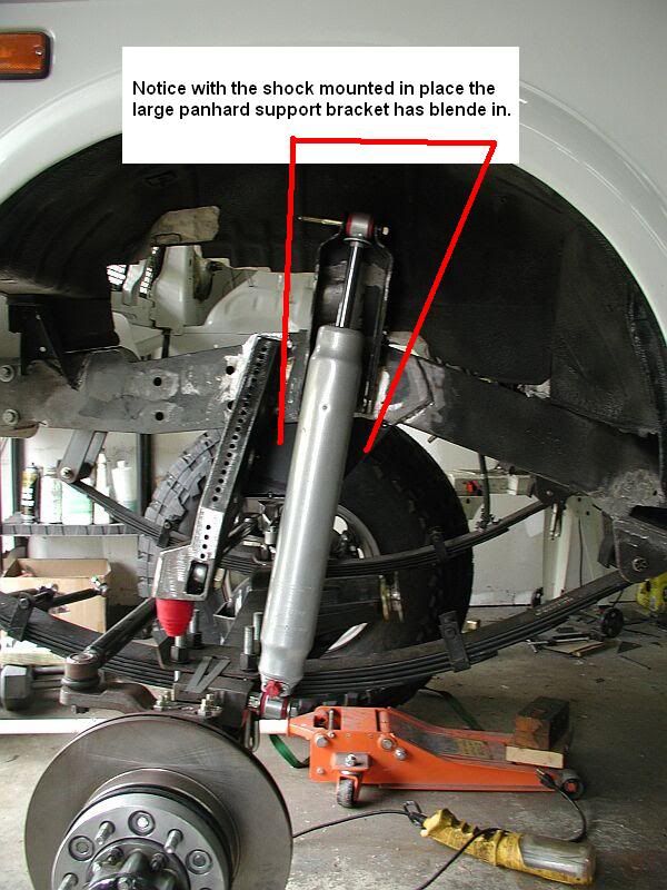
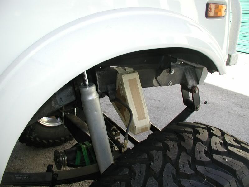
The choice was the shorter route to correct the problem because the plates were made already. The new position just happened to be my original thought. The strong need to make it more visually pleasing with everything blending at one place just took over.

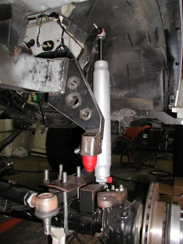
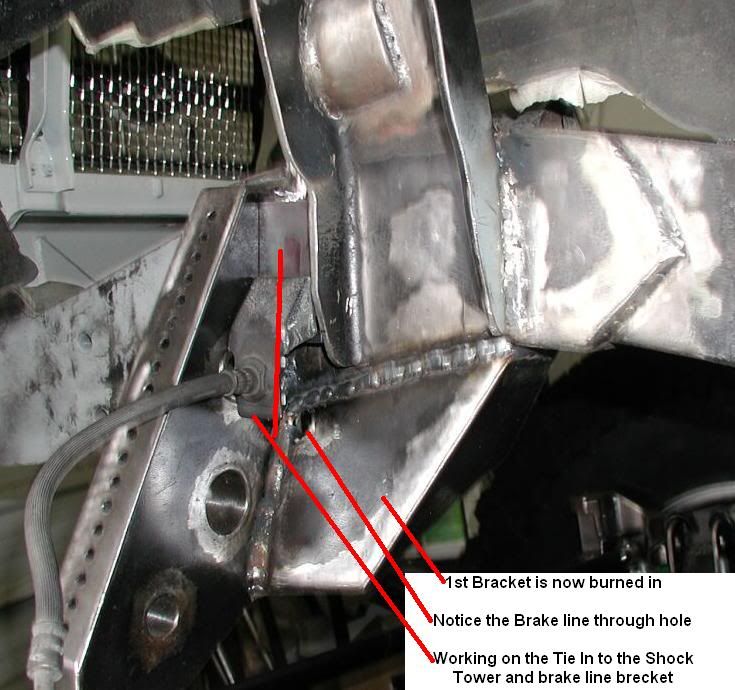
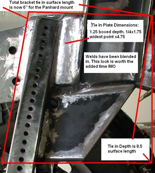
Jethrobodean also mentioned to add a fishplate to the backside of the bracket where it is being welded to the frame. This will be done as a precaution to eliminate the possibility of excess stress on this area. There was also mention to tie the top of the Panhard mount to the Ford Shock Tower for additional strength. All these were very good suggestions and will be performed as well.


Very Big Thanks to Jethrobodean for taking the time to point out something that I had contemplated on or over looked. It is always good to have an extra set of eyes looking at a complex design to accomplish the best out come.


Again it is better to be flexible ask for some input and make corrections on your design. This may require reworking or scrapping something that took a long time to make to address an issue.

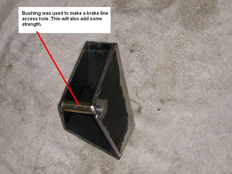
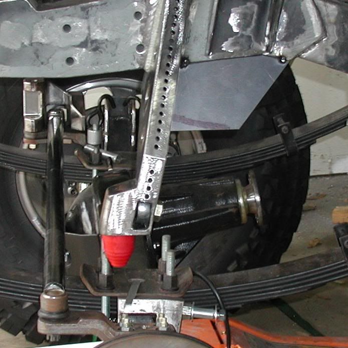
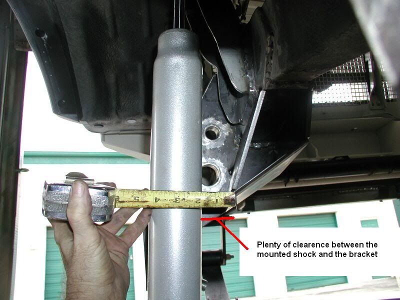
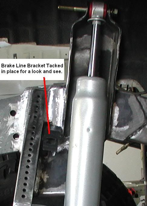
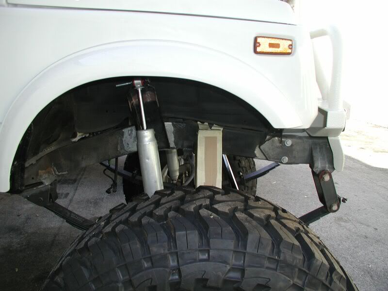
You may be wondering why the tube bushing. It has been about 9 months or so since the original brackets were removed. Good thing I had remembered that the steel brake line had to have away to get to the brake line bracket. The tube seemed to be a good solution and give some more strength to the bracket.


Image


Image


Image


Image

User avatar
TanZuk
Engaged 4wd low
Engaged 4wd low
Posts: 234
Joined: Thu Jan 05, 2012 11:17 pm
Location: Pompano Beach, Florida US

Re: Zuk on 38's

Post by TanZuk » Thu Mar 01, 2012 12:57 pm

Image

User avatar
TanZuk
Engaged 4wd low
Engaged 4wd low
Posts: 234
Joined: Thu Jan 05, 2012 11:17 pm
Location: Pompano Beach, Florida US

Re: Zuk on 38's

Post by TanZuk » Thu Mar 01, 2012 12:59 pm

Image


Image

User avatar
TanZuk
Engaged 4wd low
Engaged 4wd low
Posts: 234
Joined: Thu Jan 05, 2012 11:17 pm
Location: Pompano Beach, Florida US

Re: Zuk on 38's

Post by TanZuk » Thu Mar 01, 2012 1:00 pm

Here is my old school cardboard 2D cad mock up of the 1.25 DOM radius support bracket.

The specs are:
1.25 DOM Dia. 1/4 wall with a 4.5” inner radius at 90*.
Bottom support bracket 3/8
Top support brackets ¼ (2)


There will still be a front bracket added. Working on the pieces now.


Image

User avatar
TanZuk
Engaged 4wd low
Engaged 4wd low
Posts: 234
Joined: Thu Jan 05, 2012 11:17 pm
Location: Pompano Beach, Florida US

Re: Zuk on 38's

Post by TanZuk » Thu Mar 01, 2012 1:01 pm

Front Side 2nd Bracket is made and welded in place. You can now see the extensive amount of surface area the brackets use for strengthening the Panhard Mount. There will still be the additional 3rd round bar bracket. With all three brackets in these positions will equally distribute the load on the frame.

There will also be an additional Tie in1.25 Heim joint bar mounted between the bumpstop mounts on both sides. This will transfer any additional loads to both sides of the frame for even more strength.

Some I’m sure had some doubt of this actually working out. Hope that these Brackets and Tie in’s have helped in changing your minds.

Image


Image


Image

User avatar
TanZuk
Engaged 4wd low
Engaged 4wd low
Posts: 234
Joined: Thu Jan 05, 2012 11:17 pm
Location: Pompano Beach, Florida US

Re: Zuk on 38's

Post by TanZuk » Thu Mar 01, 2012 1:03 pm

This is the steering link and panhard bars set at 3 ½ degrees. With all the mods made the steering is now close to stock geometry.


Image


Waiting on the DS 1.25 DOM tube to be bent and that will finish this side up.


Image


Made my old school cardboard 3D cad mock up for the PS bumpstop.


Image

Image

User avatar
TanZuk
Engaged 4wd low
Engaged 4wd low
Posts: 234
Joined: Thu Jan 05, 2012 11:17 pm
Location: Pompano Beach, Florida US

Re: Zuk on 38's

Post by TanZuk » Thu Mar 01, 2012 1:09 pm

Looks like I didn't have enough info to get rid of the Muddy Boots :argh:

Post Reply